HEC-RAS 2D Terrain Preprocessing for Urban Floodplain Studies
Proper terrain preprocessing determines whether urban flood maps leak water across real barriers.
HEC-RAS 2D terrain preprocessing for urban floodplain studies is a sequence of engineering decisions. A defensible flood map depends on how the modeler conditions the terrain, selects its resolution, aligns and refines the mesh, and represents infrastructure. The central requirement is to preserve the features that control water movement without adding detail that increases computation but does not improve the result.
Why urban terrain is harder to model than it looks
Urban terrain combines narrow flow controls, large impervious areas, and drainage openings that standard elevation models often misrepresent. Curbs, walls, and embankments redirect water, while impervious surfaces accelerate runoff. Bridges and culverts complicate the surface because water passes beneath structures whose deck elevations may appear in the DEM. A plausible-looking mesh can therefore leak across an embankment, store water inside buildings, or miss a channel without any failure of the solver.
The Cimanceuri Basin study found that inundation deviation increased faster in 2D than in 1D as DEM resolution became coarser, while 1D computation time remained relatively stable. HEC-RAS is the principal model used by FEMA's National Flood Insurance Program and NOAA's National Weather Service river forecast operations through CHPS, so preprocessing errors can reach regulatory flood maps. The technical sequence begins with the terrain surface, then proceeds through resolution, mesh construction, obstruction representation, and drainage connectivity.
Building a bare-earth DTM that HEC-RAS can trust
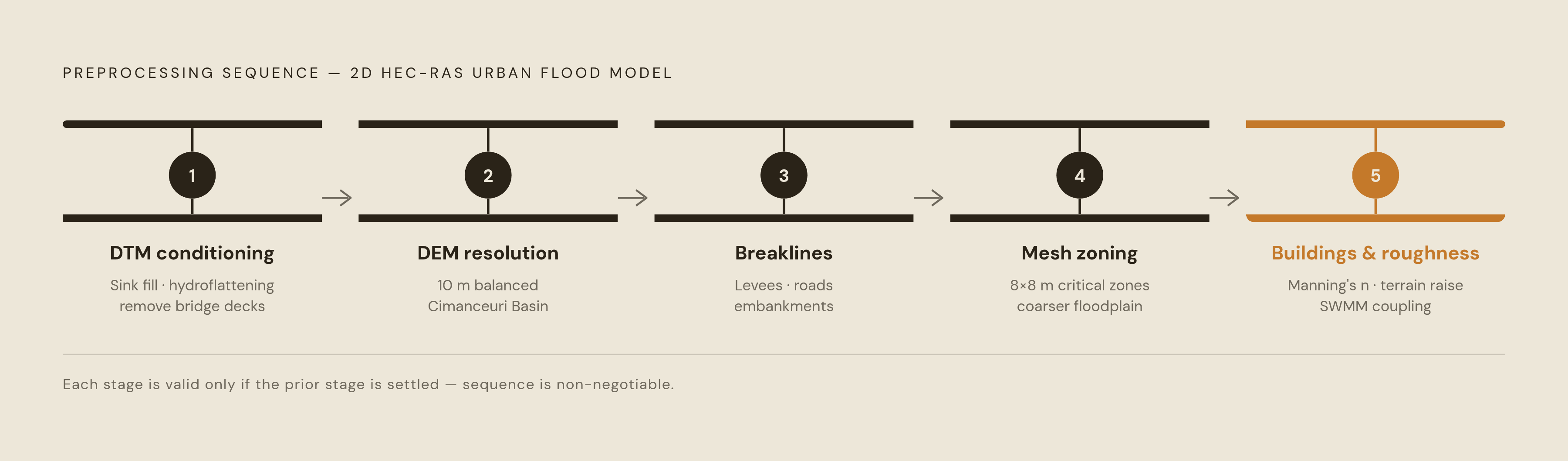
The starting surface must be a bare-earth Digital Terrain Model, with the above-ground objects found in a DSM removed. Vegetation canopy, vehicles, and building masses are removed so that the baseline represents the ground. Hydrological conditioning then removes spurious sinks and pits that would otherwise create false ponding. This is not a reason to erase real depressions, but a requirement to distinguish physical storage from artifacts before downstream decisions depend on it.
The USGS Lidar Base Specification governs hydroflattening and hydro-enforcement treatments. Hydroflattening flattens water surfaces, and where bridge abutments are clearly visible, bare-earth interpolation begins at the junction of the bridge deck and approach structure. Hydro-enforcement processes mapped waterbodies so that lakes and reservoirs are level and streams flow downhill. At bridges and culverts, removing elevations from the tops of drainage structures allows the DEM to depict the terrain beneath them, preventing the road deck from acting as a dam.
Missing bathymetry requires a separate correction because a conditioned water surface does not necessarily represent the bottom. The Moore's Mill Creek rain-on-grid study used HEC-RAS's Terrain Modification tool to represent pond and lake bottoms and correct unrealistic water retention. Buildings and infrastructure can then be deliberately incorporated as physical obstacles rather than retained as uncontrolled surface artifacts. That distinction establishes the order of work, with terrain representation settled before roughness layers are assigned.
Choosing DEM resolution: where accuracy and computation time trade off
The conditioned DTM is the surface whose resolution must now be chosen. Finer terrain generally improves spatial accuracy in 2D modeling, but the computational cost makes the finest available data an unsuitable default. The Cimanceuri Basin study tested a LiDAR DEM resampled to seven resolutions and found that the 10 m DEM provided the most balanced performance in both 1D and 2D models for event-based urban flood analysis. That result supports a deliberate trade-off, with the suitability of 10 m resolution depending on the study.
Mesh scale also affects the result independently of terrain resolution. The Wadi Al-Arj study tested several meshing pixel scales and found that a medium pixel simulation matched the validation data on which areas flooded. For operational flood management, faster runs can be more useful, while regulatory mapping of dense urban fabric needs finer resolution to keep narrow flow corridors in the model.
The defensible choice is therefore the resolution that captures the relevant terrain at an acceptable computational cost. It is not simply the smallest pixel that the source data can supply. Even a well-resolved DEM, however, cannot make the mesh honor every levee or road embankment by itself. Those controls also need breaklines to align cell faces with them.
Why HEC-RAS's subgrid architecture changes the resolution calculus
HEC-RAS separates computational cell size from terrain resolution through its subgrid pre-processor. It uses the detailed underlying terrain to calculate elevation-volume and elevation-area relationships for each cell. These relationships describe how much water a cell holds at a given water surface elevation, with the lowest parts filling first. A large computational cell can thus be partly wet and still hold the right volume of water for the finer terrain beneath it.
The hydraulic detail is held in precomputed property tables, so it depends on more than the number of cells. Placing cell faces along roads, high ground, and walls can further improve hydraulic calculations while keeping the number of cells down.
The limit is a controlling feature narrower than the cell spanning it. Subgrid storage information alone cannot make that cell behave as though a properly aligned barrier divides it. Fine terrain can show the crest even when the mesh fails to capture how it controls flow. Breaklines address that geometric limit.
Breakline placement: the most consequential call in urban mesh construction
Breaklines force cell faces to line up along a chosen terrain line. That alignment allows the hydraulic property tables on either side to represent a barrier or channel. The HEC-RAS User's Manual specifies their use at locations that control or block flow, including levees, roads, natural embankments, and high ground.
A levee only 15 feet wide inside cells 50 feet wide shows how this can fail. Without a breakline, cell faces can span the levee, allowing water to “leak” through a barrier that exists in the elevation data. The error demonstrates that the computational geometry has not preserved the barrier.
Choosing the features that control how water moves takes judgment. Too few breaklines leave important controls unresolved, but tracing every undulation makes the mesh unmanageable. Breaklines are therefore a targeted treatment for barriers and channels. The distinction matters especially in urban areas, where many visible features compete for attention but do not carry equal hydraulic significance.
Channel hydro-enforcement also depends on the order of operations. A cell protection radius is applied before enforcing stream centerline or channel bank breaklines so that the hydro-enforcing geometry survives mesh refinement. Once those controls are fixed, cell-size zoning can distribute refinement around them.
Mesh cell-size zoning: matching refinement to what the terrain actually demands
A variable mesh concentrates fine cells where flow dynamics are complex and uses coarser cells where extra refinement contributes less. Channels, levees, and road crossings need attention because their shape controls how water moves through them. Open floodplain can often retain larger cells while benefiting from the underlying subgrid terrain information. The objective is to spend computational effort where it changes the hydraulic result.
The Ungheni study applied finer cells at critical features, including minor channels, roads, and levees, and used 8×8 m cells in less hydraulically sensitive floodplain areas. That example supports spatially selective refinement rather than a single cell size across the study area. It also shows why the cell-size decision follows identification of the controlling features. Without that hierarchy, refinement can become a uniform increase in model size unrelated to terrain demands.
Refinement regions extend this control beyond individual breaklines by assigning a target cell size to a defined area. They allow transition zones between fine and coarse mesh, avoiding abrupt cell-size jumps that can introduce numerical instability. The resulting mesh is judged by whether it resolves the required controls.
Representing buildings and roughness: two methods with different consequences
To represent buildings, the model must either add resistance or create a physical obstruction. High-roughness regions represent buildings with elevated Manning's n and are simpler to implement. However, they still allow storage inside the obstruction, which is physically wrong.
Direct terrain modification instead raises building footprints in the DTM so that the terrain blocks flow. This method is recommended where building representation materially affects results, particularly downstream hydrographs. The choice therefore depends on the hydraulic consequence of the obstruction rather than a preference for one preprocessing method.
Roughness assignment follows that physical representation. Concrete channels, grass and vegetation, and urban areas with buildings have substantially different resistance, so land-use-based Manning's n values affect the model as a whole. Roughness calibration must precede full scenario simulations because it influences flood wave propagation, peak attenuation, and hydrograph timing. The Ungheni study included buildings, levees, and detailed land-use roughness to model local hydraulic dynamics and assess which buildings and infrastructure were at risk. Even a correctly roughened and meshed surface, however, cannot by itself represent stormwater moving underground.
Rain-on-grid and coupled drainage: when surface-only modeling is not enough
Rain-on-grid applies precipitation directly to the 2D mesh and routes the resulting runoff across the terrain without requiring a separate upstream hydrological model. The Banyakan study used this approach in a watershed under land-use pressure from airport and toll road construction. Its practicality does not remove the need to examine how drainage is represented. HEC-RAS documentation states that infiltration is subtracted directly from the precipitation hyetograph rather than calculated as a function of surface water depth, which affects ponding behavior and longer-duration simulation accuracy.
Underground conveyance presents a different limitation because it redirects water beyond the visible terrain. HEC-RAS versions before 6.6 had no built-in way to represent a subsurface pipe-network, while version 6.6, released in 2024, added integrated pipe network modeling in beta form. A surface-only model still omits the function of inlets, storm sewers, and detention systems where those assets materially control flooding. The final preprocessing step is therefore to judge whether the prepared surface captures the drainage pathways that matter to the study.
Coupled SWMM–HEC-RAS 2D modeling feeds the flooding rate calculated at each SWMM pipe-network node into HEC-RAS 2D to calculate changing flood depths and velocities. The Karaj City study applied this approach where deteriorating and aging drainage networks were associated with higher hazard magnitudes in southern areas. Dense, aging underground infrastructure favors coupling, whereas watershed-scale floodplain extent mapping may not require it.
How AI is changing the speed of these preprocessing decisions for AEC firms
These preprocessing tasks consume substantial engineering time because they combine repeated operations with consequential judgment. Their sequence is nevertheless structured, with DEM conditioning preceding roughness assignment and breakline placement preceding mesh refinement. That order makes parts of the work suitable for AI-assisted execution, reducing repeated manual iteration.
AEC-specific AI tools working inside existing software environments, including Civil 3D, HEC-RAS, and OpenRoads, allow preprocessing tasks to be delegated without requiring a separate workflow. The engineer stays in control of which tasks to assign and reviews and approves the work. For small and mid-size civil and water resources firms, cutting the project hours spent on preprocessing can change how many projects a team can take on. That benefit depends on keeping engineering judgment sound as terrain and mesh files are produced faster.
Accountability remains with the licensed professional. Every prepared terrain, mesh, roughness layer, and coupling decision still requires review and approval, and stamp authority does not transfer to the AI. Assistance can accelerate a well-defined sequence, but it cannot make an unresolved flow control defensible. The final flood map remains only as reliable as the engineering decisions encoded in the model beneath it.
Sources
- Influence of DEM Spatial Resolution on the Accuracy and Computational Efficiency of HEC-RAS 1D and 2D Flood Inundation Modelling: A Case Study of the Cimanceuri Basin, Indonesia
- Flood Risk Prediction and Management by Integrating GIS and HEC-RAS 2D Hydraulic Modelling: A Case Study of Ungheni, Iasi County, Romania
- IOP Conference Series: Earth and Environmental Science PAPER • OPEN ACCESS
- A new approach for urban flood risk assessment using coupled SWMM–HEC-RAS-2D model - ScienceDirect
- Flood Inundation Mapping Using HEC-RAS 2D Modeling and Examining the Impact of Changes in the Model-Meshing Pixel Scale on the Final Output